 serin labs
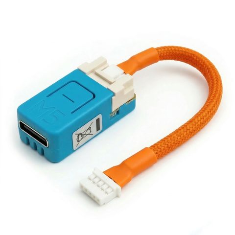
This is the physical installation procedure for a controller and assembled CN105-to-Grove cable. It is shared by all three firmware choices. If you are making a cable, build and check it against the wiring reference first.
1 Prepare for installation
- Confirm model compatibility and that the CN105 port is available. The controller cannot share that port with an existing wired accessory; CN105 splitters are not supported.
- Install your chosen firmware over USB before fitting the controller. Disconnect the USB cable afterward.
- Have a screwdriver and the controller with its cable ready. Read the safety and installation information.
Switch off power at the breaker, not just at the remote. The control board carries line voltage. Leave power off until the cover is back on. If you are not comfortable working inside the unit, have an HVAC technician make the connection.
2 Connect and position the controller
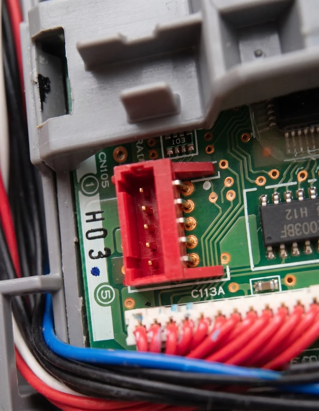
- With power off, open the indoor unit's cover and locate the main control board. Find the five-pin connector labeled CN105, usually red and sometimes white. Do not substitute CN110.
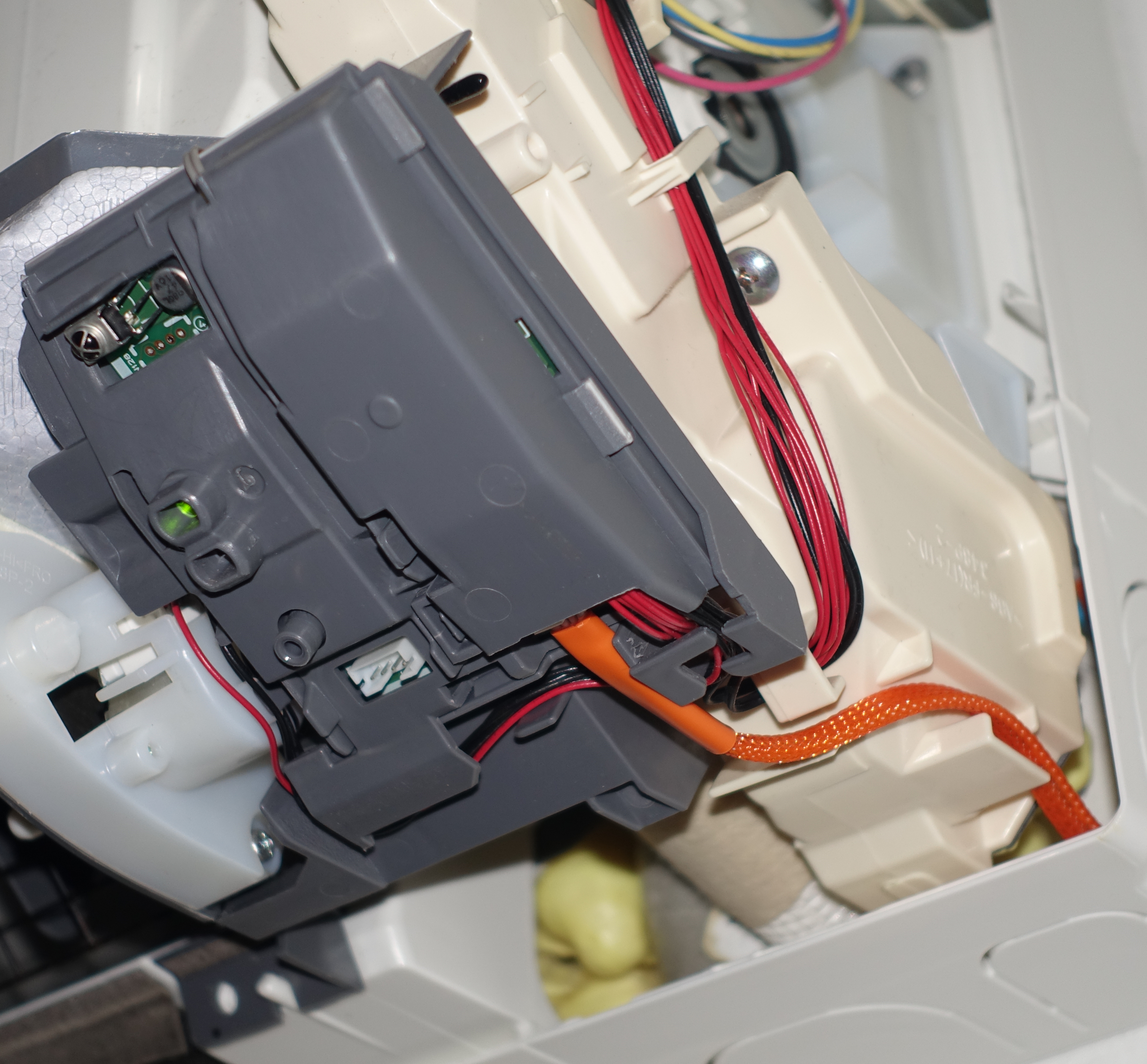
- Seat the cable's CN105 connector in the unit and the Grove connector in the controller. Check orientation against the connector and board markings; do not force either connector. The wiring reference shows both ends.
- Position the controller and cable clear of the fan, heat exchanger fins, and condensate tray. Ensure the cover will not pinch the cable.
3 Replace the cover and restore power
Check that the connectors are fully seated and the cable is clear, reinstall the cover, then restore power at the breaker. CN105 supplies power to the controller; a USB power supply is not needed inside the unit.
On HomeKit-compatible and Matter-compatible firmware, the status light shows startup and connection state. ESPHome uses the RGB LED as a controllable light entity, so those status colors do not apply.
Before moving on: The cover is secure, power is restored, and the controller is powered through CN105.