 serin labs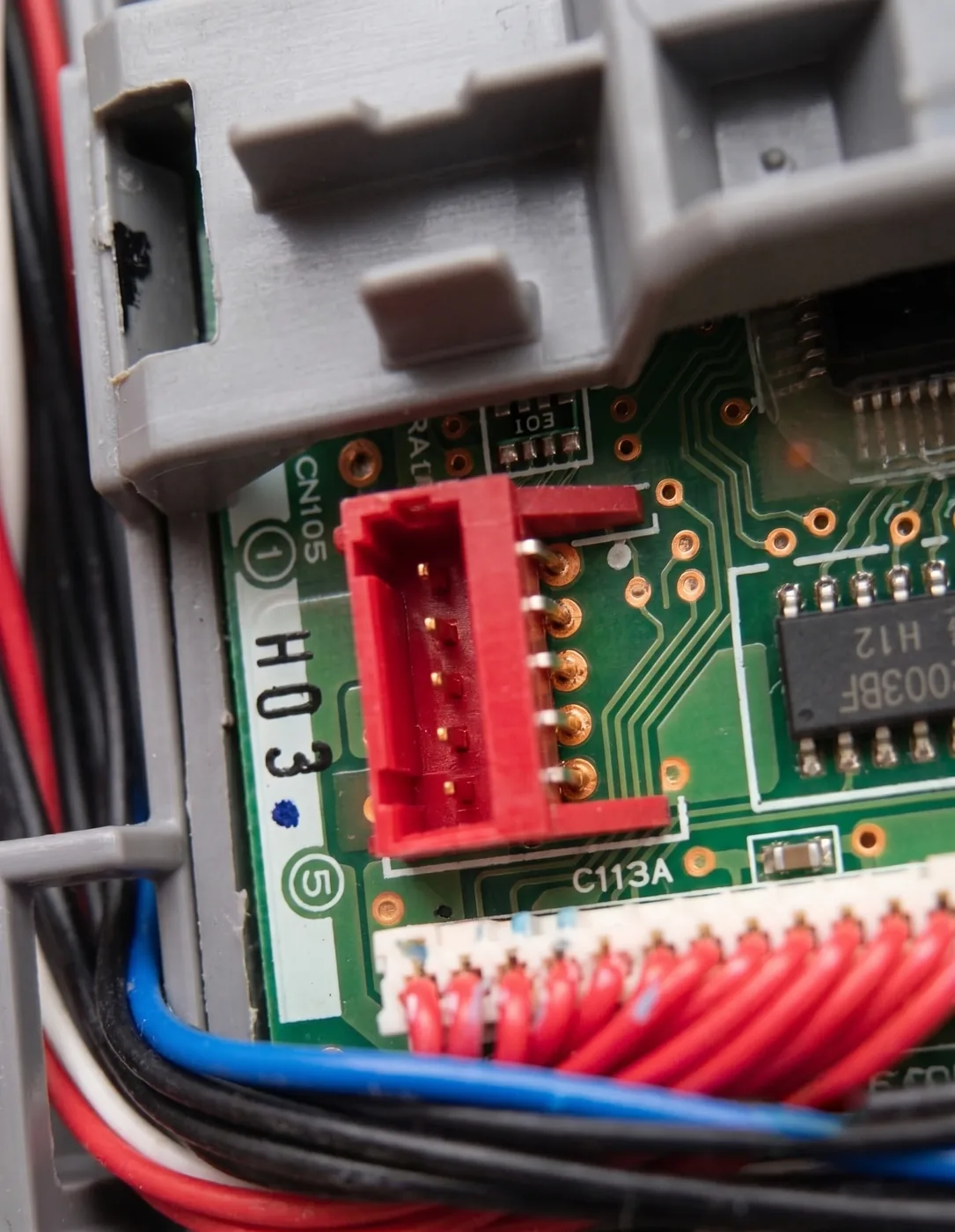
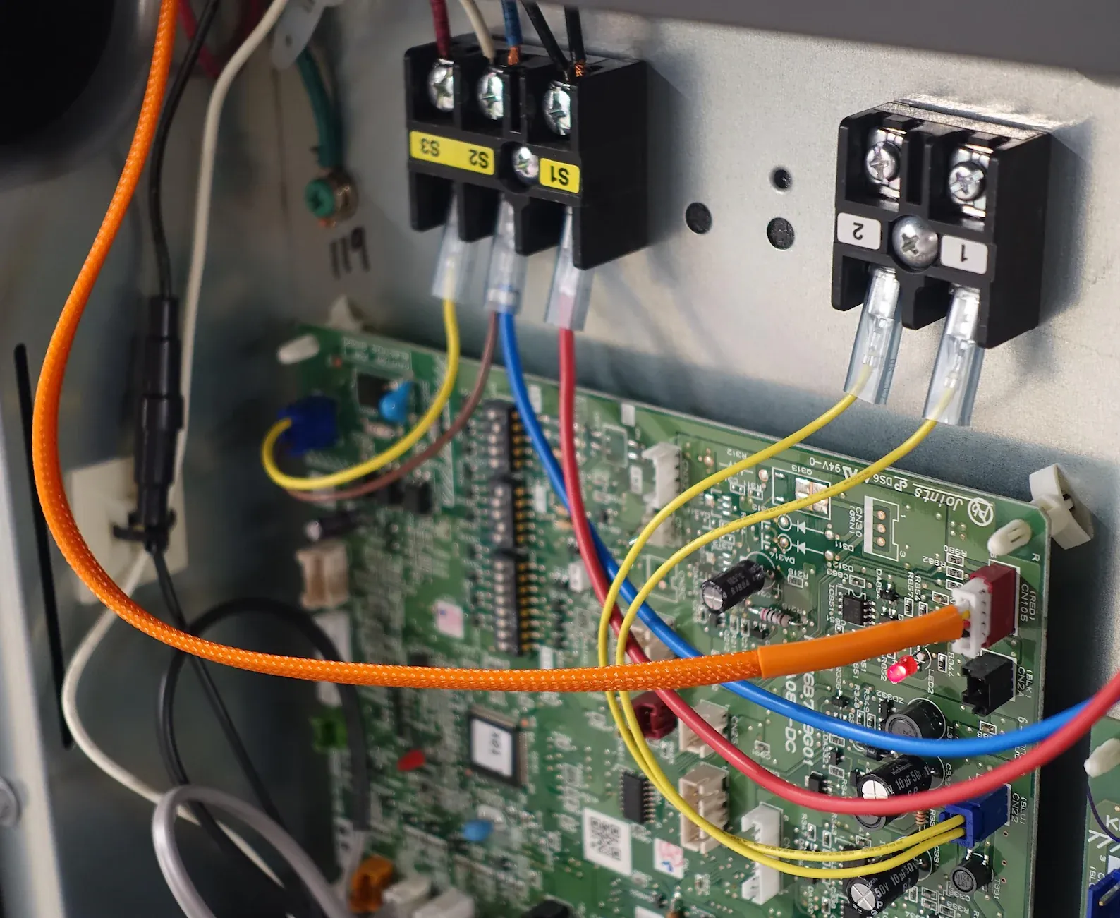
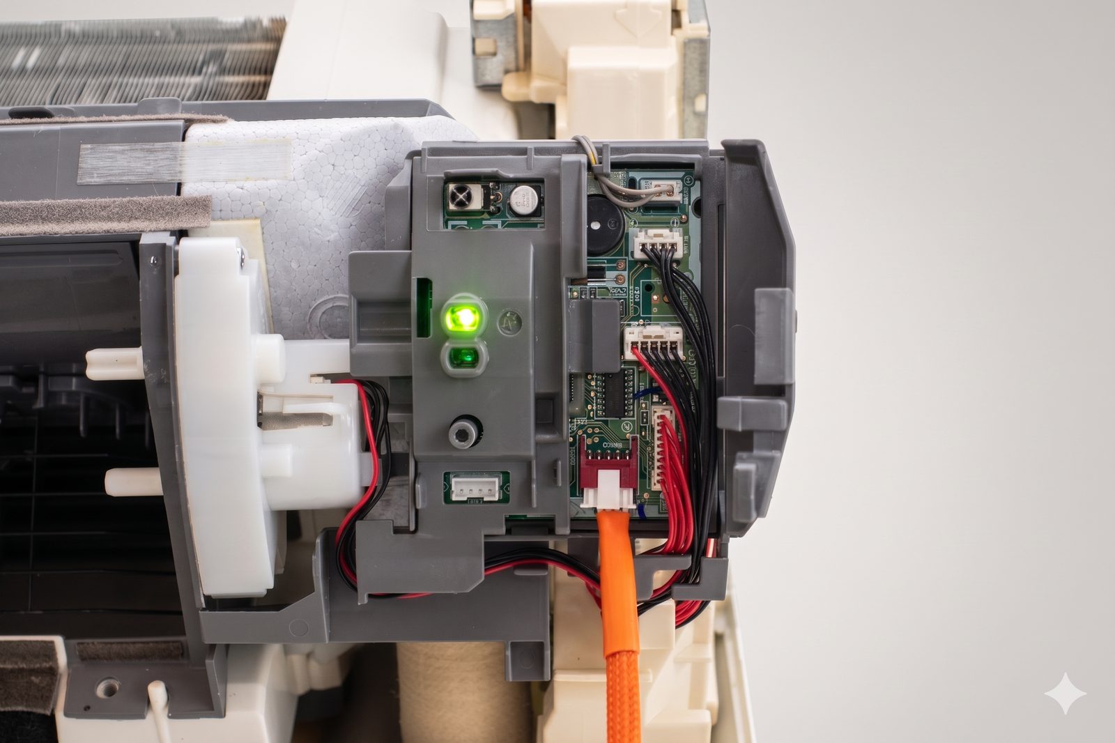
This reference shows every connection between the CN105 service port on a Mitsubishi indoor unit and the Grove HY2.0 connector on an M5Stack Atom S3 Lite or NanoC6. It identifies each conductor, both connector housings, and the checks to complete before restoring power.
Crimp your own from the parts below, or buy the cable assembled and tested.
On this page
Wiring diagram
Scroll sideways to see the full diagram.
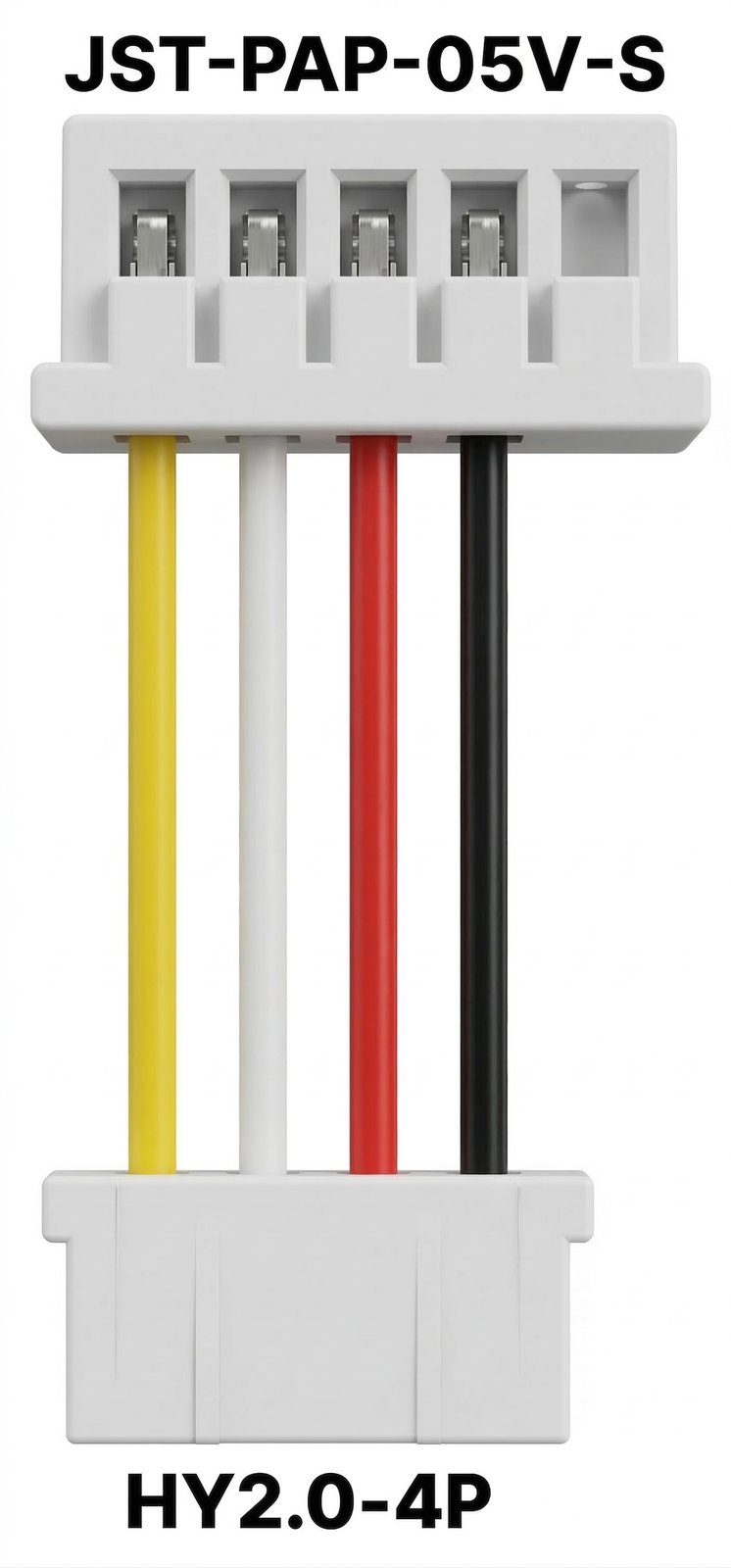
| Wire | CN105 | Grove | Carries |
|---|---|---|---|
| Black | 2 · GND | 1 · GND | Ground reference |
| Red | 3 · 5V | 2 · 5V | 5 V from the HVAC |
| White | 4 · TX | 3 · RX GPIO 2 | HVAC → board |
| Yellow | 5 · RX | 4 · TX GPIO 1 | Board → HVAC |
| none | 1 · 12V | — | Leave empty |
Check before you power it on
- Cavity 1 on the CN105 end is empty, and the ▲ lines up with the 1 on the board silkscreen.
- Black and red are not swapped; reversed power is the one mistake that damages a board.
- Unit power is off at the breaker before the connector goes in or comes out.
Pinout reference
CN105 · JST-PAP-05V-S
| Pin | Signal | Description |
|---|---|---|
| 1 | 12V | Not used |
| 2 | GND | Ground |
| 3 | 5V | 5V Power |
| 4 | TX | Data output from HVAC (5V logic) |
| 5 | RX | Data input to HVAC (5V logic) |
Grove · HY2.0-4P Atom S3 Lite, NanoC6
| Pin | Signal | Description |
|---|---|---|
| 1 | G | Ground (connects to ESP32 GND) |
| 2 | 5V | 5V Power (connects to ESP32 5V/VCC) |
| 3 | G2 | RX (connects to ESP32 UART RX pin) |
| 4 | G1 | TX (connects to ESP32 UART TX pin) |
Build your own
Two connector housings and four conductors. Crimp the pinout above into these:
The parts list covers the boards these connect to.
Safety
Turn off power to the indoor unit at the breaker, not just at the remote, before connecting or disconnecting any cable, and leave it off until the cover is back on. CN105 is the only connector that needs to be handled; the rest of the control board carries line voltage.
References
Ready-made alternative
Buy the cable assembled
The same harness, built and electrically tested, from $8, in 20 cm and 50 cm. Or take the Serin Controller, which is an ESP32 board with this cable already attached, from $35.